ESP32 Pinout: Which GPIO should you use when?
The ESP32 has a lot of GPIOs with multiple functions.But not all of them can be used for every function and some can even crash your device if you use them wrong.
This page gives you an easy overview to avoid these issue and get the most out of your board.
Pin table
This table shows you what function a GPIO pin is capable of doing. if a function is marked in orange, it might be used for this function, but you have to be careful. For example ADC pins with an orange 2 can not be used, if Wi-Fi is enabled. If the GPIO pin number is orange, the pin is a strapping pin| GPIO | Input | Output | ADC | Notes |
| 0 | pulled up | OK | 2 | selectes the boot mode |
| 1 | TX pin | OK | x | debug output at boot |
| 2 | OK | OK | 2 | |
| 3 | OK | RX pin | x | HIGH at boot |
| 4 | OK | OK | 2 | |
| 5 | OK | OK | x | outputs PWM signal at boot |
| 6 | x | x | x | connected to the integrated flash |
| 7 | x | x | x | connected to the integrated flash |
| 8 | x | x | x | connected to the integrated flash |
| 9 | x | x | x | connected to the integrated flash |
| 10 | x | x | x | connected to the integrated flash |
| 11 | x | x | x | connected to the integrated flash |
| 12 | OK | OK | 2 | boot fail if pulled high |
| 13 | OK | OK | 2 | |
| 14 | OK | OK | 2 | outputs PWM signal at boot |
| 15 | OK | OK | 2 | outputs PWM signal at boot |
| 16 | OK | OK | x | |
| 17 | OK | OK | x | |
| 18 | OK | OK | x | |
| 19 | OK | OK | x | |
| 21 | OK | OK | x | |
| 22 | OK | OK | x | |
| 23 | OK | OK | x | |
| 25 | OK | OK | 2 | |
| 26 | OK | OK | 2 | |
| 27 | OK | OK | 2 | |
| 32 | OK | OK | 1 | |
| 33 | OK | OK | 1 | |
| 34 | OK | x | 1 | input only |
| 35 | OK | x | 1 | input only |
| 36 | OK | x | 1 | input only |
| 39 | OK | x | 1 | input only |
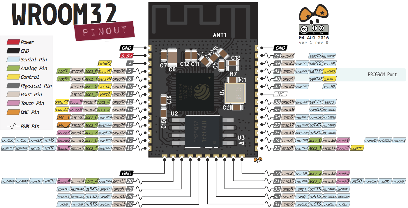
ESP WROOM 32
Strapping Pins
The ESP32 chip has the following strapping pins:•GPIO 0 (used to put the board into bootloader)
•GPIO 2
•GPIO 4
•GPIO 5 (must be HIGH during boot)
•GPIO 12 (must be LOW during boot)
•GPIO 15 (must be HIGH during boot)
Most Breakout Boards control these pins automatically and if you don't want any trouble with them, avoid using them for anything.
Analog to Digital Converter (ADC)
The ESP32 has 18 12 bit ADC inputs. Please note that all ADC2 pins can not be used if Wi-Fi is enabled!•GPIO 36 ADC1_CH0
•GPIO 37 ADC1_CH1
•GPIO 38 ADC1_CH2
•GPIO 39 ADC1_CH3
•GPIO 32 ADC1_CH4
•GPIO 33 ADC1_CH5
•GPIO 34 ADC1_CH6
•GPIO 35 ADC1_CH7
•GPIO 4 ADC2_CH0
•GPIO 0 ADC2_CH1
•GPIO 2 ADC2_CH2
•GPIO 15 ADC2_CH3
•GPIO 13 ADC2_CH4
•GPIO 12 ADC2_CH5
•GPIO 14 ADC2_CH6
•GPIO 27 ADC2_CH7
•GPIO 25 ADC2_CH8
•GPIO 26 ADC2_CH9
If you find any errors or have a suggestion for new content, feel free to contact me at jonas.niesner@gmail.com